Introduction
In this project, we extended the path tracing capabilities created in the previous part to render advanced materials, including mirrors, glass, and metal.
This primarily involved implementing reflection, refraction, and microfacet material BSDF’s.
Part 1: Mirror and Glass Materials
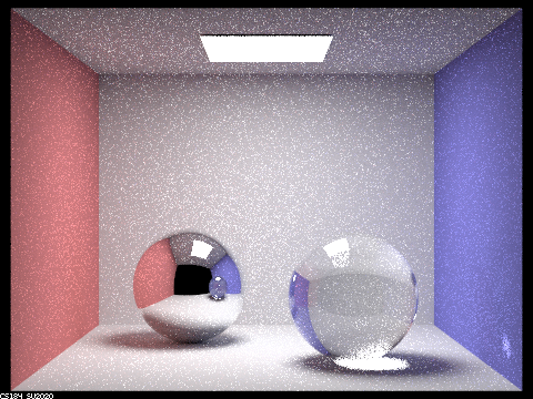
Below are some demo renders of CBspheres.dae with varying ray depths.
Max Ray Depth: 0
./pathtracer -t 8 -s 64 -l 4 -m 0 -f spheres_0.png -r 480 360 ../dae/sky/CBspheres.dae

For m=1, there are also no multibounce effects since only one bounce is rendered
Max Ray Depth: 2
./pathtracer -t 8 -s 64 -l 4 -m 2 -f spheres_2.png -r 480 360 ../dae/sky/CBspheres.dae
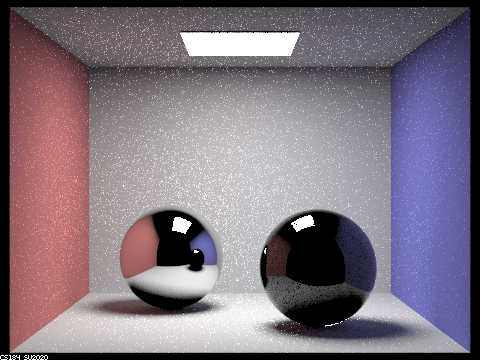
m=2 is when we begin to see some reflection and refraction effects. However, all of the multibounce materials appear black in the reflection since further rays do not bounce off of this image.
Max Ray Depth: 3
./pathtracer -t 8 -s 64 -l 4 -m 3 -f spheres_3.png -r 480 360 ../dae/sky/CBspheres.dae
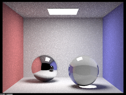
At m=3, we begin to see a reflection within the reflection. As expected, this secondary reflection is black since rays do not bounce further than this.
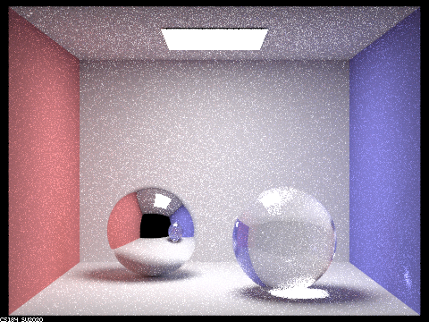
Max Ray Depth: 4
./pathtracer -t 8 -s 64 -l 4 -m 4 -f spheres_4.png -r 480 360 ../dae/sky/CBspheres.dae
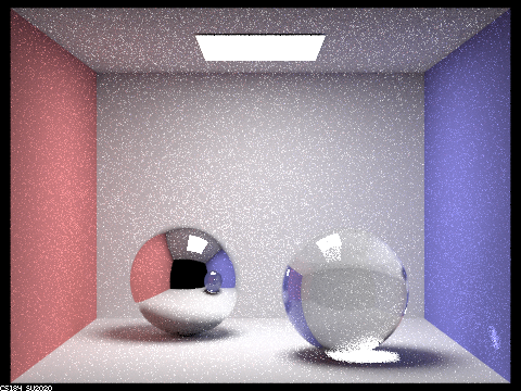
At m=4, the secondary reflection is properly rendered to the point where the render becomes nearly complete.
Max Ray Depth: 5
./pathtracer -t 8 -s 64 -l 4 -m 5 -f spheres_5.png -r 480 360 ../dae/sky/CBspheres.dae
There are no more significant differences at m=5 from the previous depth, although the image does become slightly clearer.
Max Ray Depth: 100
./pathtracer -t 8 -s 64 -l 4 -m 100 -f spheres_100.png -r 480 360 ../dae/sky/CBspheres.dae
There are also no significant differences for m=100 compared to m=5.
Part 2: Microfacet Material
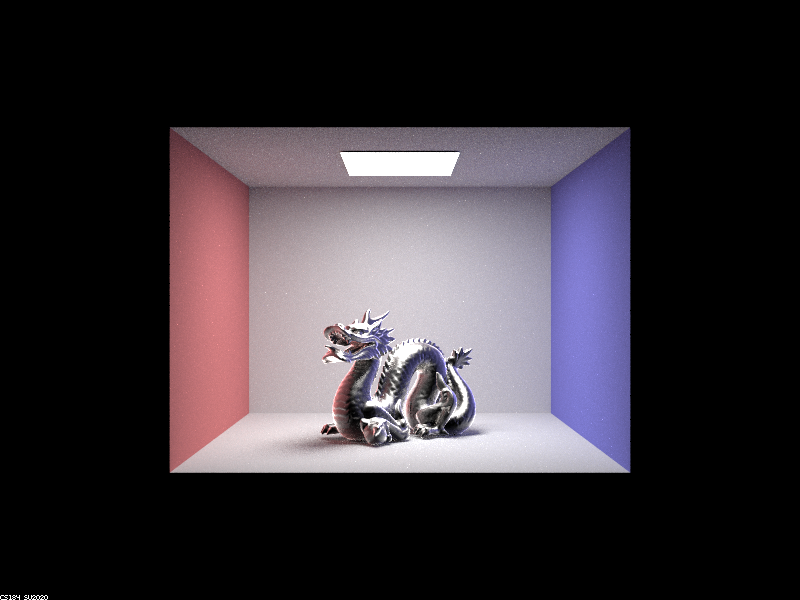
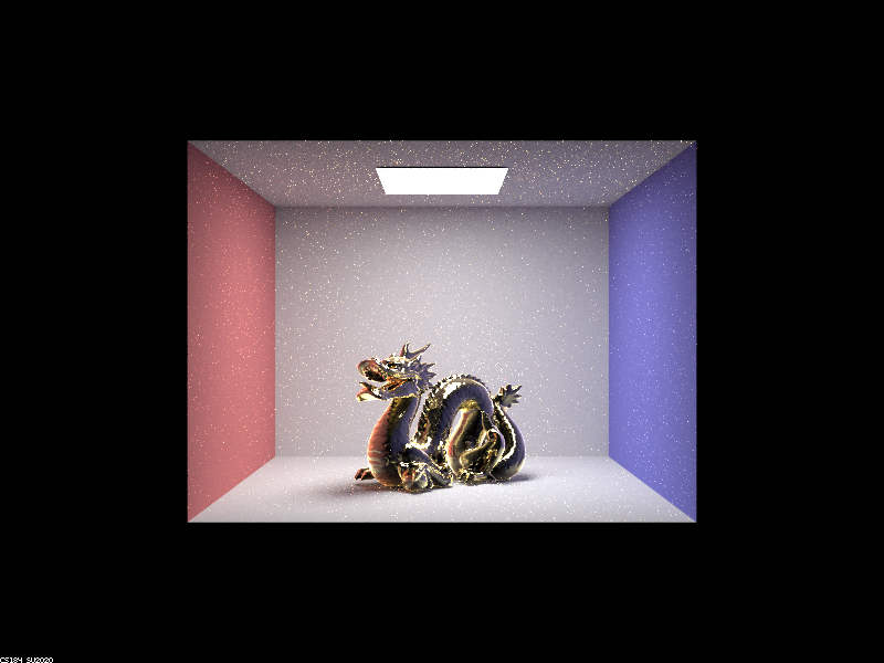
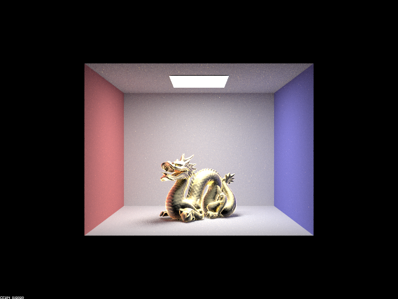
Dragon demos
alpha: 0.005 (edited microfacet property in .dae file)
./pathtracer -t 8 -s 128 -l 1 -m 5 -f dragon_005.png ../dae/sky/CBdragon_microfacet_au_005.dae

alpha: 0.05
./pathtracer -t 8 -s 128 -l 1 -m 5 -f dragon_05.png ../dae/sky/CBdragon_microfacet_au_05.dae
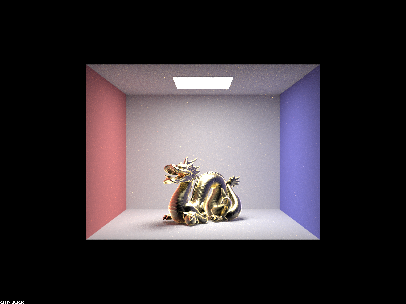
alpha: 0.25
./pathtracer -t 8 -s 128 -l 1 -m 5 -f dragon_25.png ../dae/sky/CBdragon_microfacet_au_025.dae
alpha: 0.5
./pathtracer -t 8 -s 128 -l 1 -m 5 -f dragon_5.png ../dae/sky/CBdragon_microfacet_au_5.dae
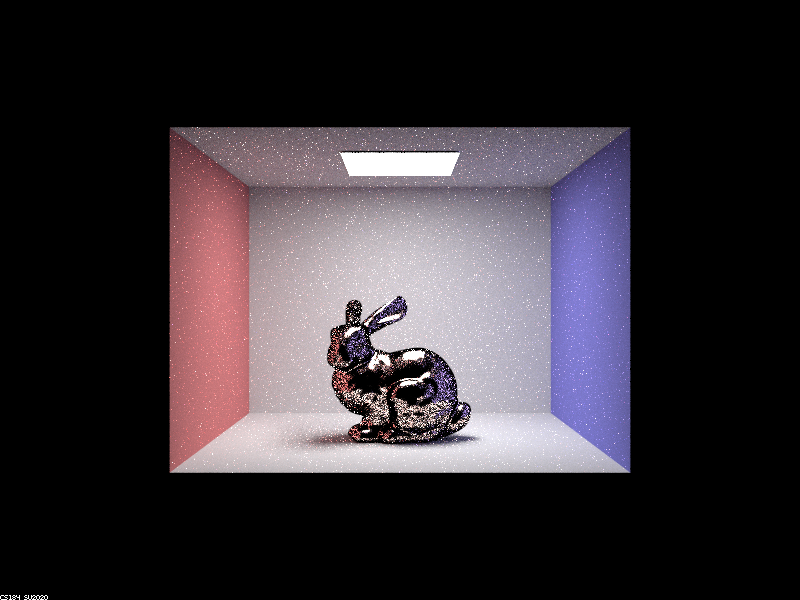
Bunny demos
Below, we see the comparison between hemisphere sampling and importance sampling. We can observe that at the same number of samples taken, the image generated with importance sampling appears far more complete, whereas the hemisphere sampled image still has many areas that are not fully rendered. This is because hemisphere sampling results in many rejected samples, while importance sampling will prioritize choosing microfacet directions that are actually realistic.
./pathtracer -t 8 -s 64 -l 1 -m 5 -f bunny_demo.png ../dae/sky/CBbunny_microfacet_cu.dae
With hemisphere sampling:
With importance sampling:

Other Material demo
Here’s a dragon made of cobalt (alpha = 0.25, n = (2.19, 2.05, 1.81); k = (4.11, 3.82, 3.41)):
./pathtracer -t 8 -s 128 -l 1 -m 5 -f dragon_co.png ../dae/sky/CBdragon_microfacet_co.dae