Overview
In this project, we created a simple rasterization engine to draw basic lines, triangles, and shapes defined in SVG format, and apply color and texture to them.
In addition, we implemented multiple sampling methods, both for changing texture filtering on pixels and on mipmap levels.
Over the course of this project, we learned about how to apply the formulas we learned in class to actually generate images and render them to the screen based on a set of coordinates and instructions.
Section I: Rasterization
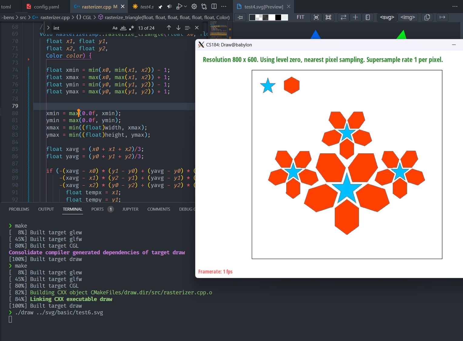
Task 1: Drawing Triangles
Raterization is a technique to draw 3D objects onto a 2D screen. At its most basic, rasterizing triangles works by sampling from every point in the object space corresponding to a pixel on the screen, and checking to see if that point is inside of the triangle. If it is inside the triangle, then the pixel should be colored the color of the triangle, otherwise the pixel is not colored.
Our algorithm works by first defining the bounding box of the triangle using the min and max of the three vertices along the x and y coordinates (or the edge of the display if the triangle is cut off). Then we check every pixel within that space for if it is inside the triangle. Trivially, our algorithm is no worse than one that checks each sample within the bounding box since it is exactly this algorithm.
To determine whether the point is actually inside of the triangle, we use the three-line test using the same method as described in lecture. Essentially, this works by treating each line as the boundary of a half-plane, where the half-plane includese the area within the triangle. If a point is inside all three half-planes, then it must be inside of the triangle.
Here is the condition to check one of the lines:
-(sx - x0) * (y1 - y0) + (sy - y0) * (x1 - x0) >= 0
We then repeat this for the other two pairs (1 and 2; 2 and 0) in that order.
One issue is that this condition assumes that the points (labelled 0, 1, 2) are labelled in a clockwise direction, where 1 is clockwise from 0 and so on.
To check if the points are clockwise, we take a point that we know is guaranteed to be within the triangle (namely, the center of the triangle $((x_0 + x_1 + x_2)/3, (y_0+y_1+y_2)/3 )$), and make sure it passes the three-line test. If it fails, then we rearrange the points by swapping $(x_1, y_1)$ with $(x_2, y_2)$ to make them clockwise.
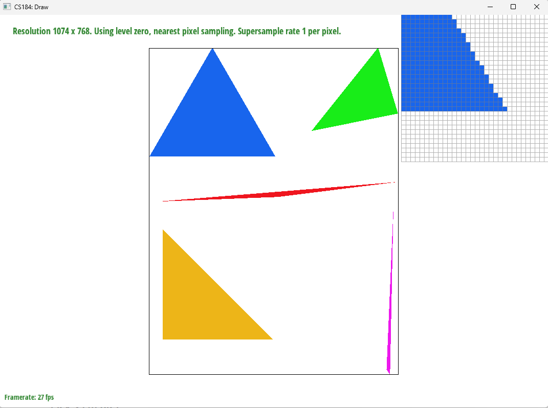
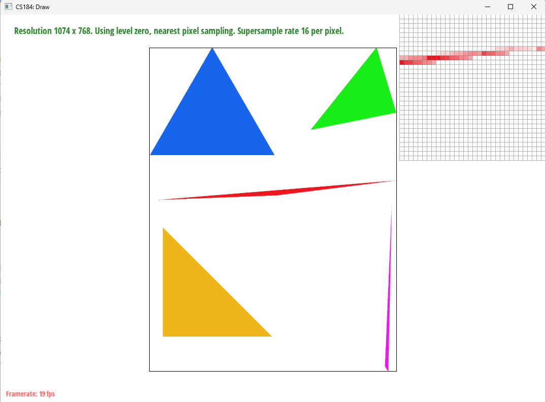
The image below illustrates how triangles are rendered (before antialiasing):
Task 2: Antialiasing
For supersampling we sampled the image multiple times within each pixel and then averagd the resulting color for the renderd image. Our supersampling technique sampled evenly within the pixel in a grid formation and saved the pixel’s colors to a sample buffer of size of image * supersampling rate. This buffer stored all the samples for a specific pixel in sequence, which allowed for easier math for sampling and rendering.
Supersampling is useful as an antialiasing technique because it smooths out edges by blending the sharp cutoffs. For example, without supersampling, a triangle edge may dip inbetween the sample points of neighboring pixels leading to jaggies, supersampling allows that edge to be captured in some of the samples, leading to a smoother transition between being inside and outside of the shape.
Our rasterization pipeline changed to sample multiple times according to the supersampling rate and then also render pixels by average the colors for the multiple samples within that pixel. Additionally because liens and points were not supersampled, the fill_pixel method was changed to fill all the samples within a pixel to the corresponding color during supersampling.
This process allowed us to antialias our triangles by having a smoother edge. As shown in the image, instead of a sharp cutoff, where the tail end of the triangle forms some small islands of pixels, the supersampled images have a smooth transition into lighter shades of red to display the edge of the triangle.
Below are some comparison images.
1x (no supersampling):
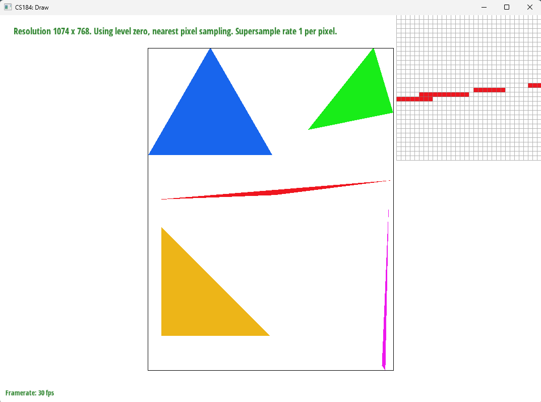
4x supersampling:

16x supersampling:
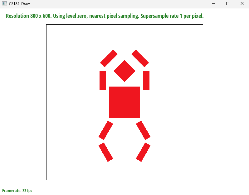
Task 3: Transforms
We modified the robot to perform a pirouette motion. The toes (or rather simply lower legs) point inward as the arms point skyward, as if the robot was performing a pirouette.
Section II: Sampling
Task 4: Barycentric coordinates
Barycentric coordinates are an alternative coordinate scheme in which a point is defined by its relative proximity to the three vertices of a triangle.
Converting from 2D space to barycentric coordinates involves computing the following values:
$$(x, y) = \alpha A + \beta B + \gamma C; \alpha + \beta + \gamma = 1$$
where $A,B,C$ are the 2D coordinates of the vertices, and $\alpha, \beta, \gamma$ are the barycentric coordinates that represent how close a point is to the vertices $A,B,$ and $C$ repsectively.
Barycentric coordinates are especially useful for interpolation, since they can represent any arbitrary blend of nearby values as illustrated by the triangle below (credit: Lecture 5, slide 24):
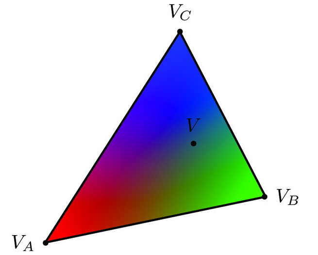
In the example above, $V_A$ represents the color red, $V_B$ represents green, and $V_C$ represents blue. As a point in the triangle approaches one of these vertices, the color at that point becomes closer to the color of that vertex. Conversely, towards the center of the triangle, the colors blend into grey as it has equal components of red, green, and blue.
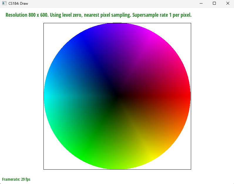
Here’s the color wheel that smooth color interpolation creates using barycentric coordinates:
Task 5: Pixel Sampling
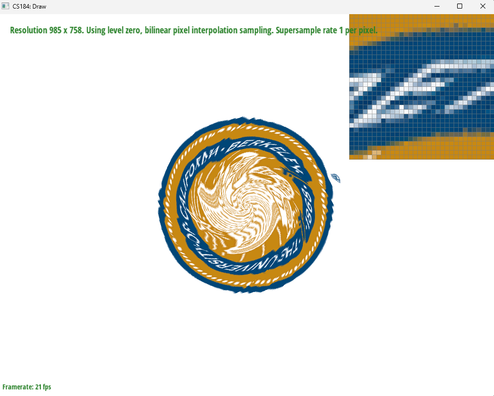
Pixel sampling is the process of using sampling to convert between pixels in screen space, and texels in texture space. For texture mapping, we sampled every point of a texture relative to a point within each triangle using barycentric coordinates. This gave us the color for each pixel within the triangle as sampled from the corresponding texel in the texture. In the project we implemented both nearest and bilinear pixel sampling. Neareset is simpler; the sample from the texture is merely a sample of the nearest texel within the texture. This is easy to implement but may suffer from aliasing because each pixel is taken only from one sample, and so may alias across sharp color transitions within the texture. Bilinear pixel sampling aims to mitigate texture aliasing by sampling multiple texels around the desired pixel. Then the colors are smoothed using bilinear interpolation, which uses the relative distances from the desired pixel to the four neighboring texels, and weights the color values based on these distances.
| Nearest | Bilinear | |
|---|---|---|
| 1x (No supersampling) | 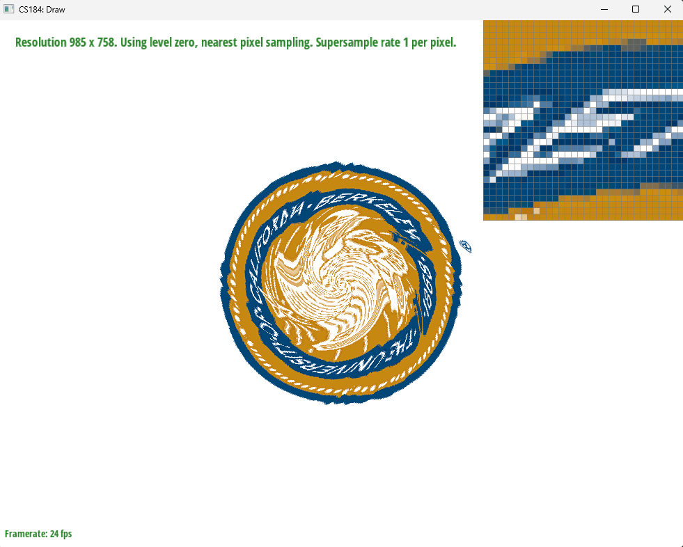
|
|
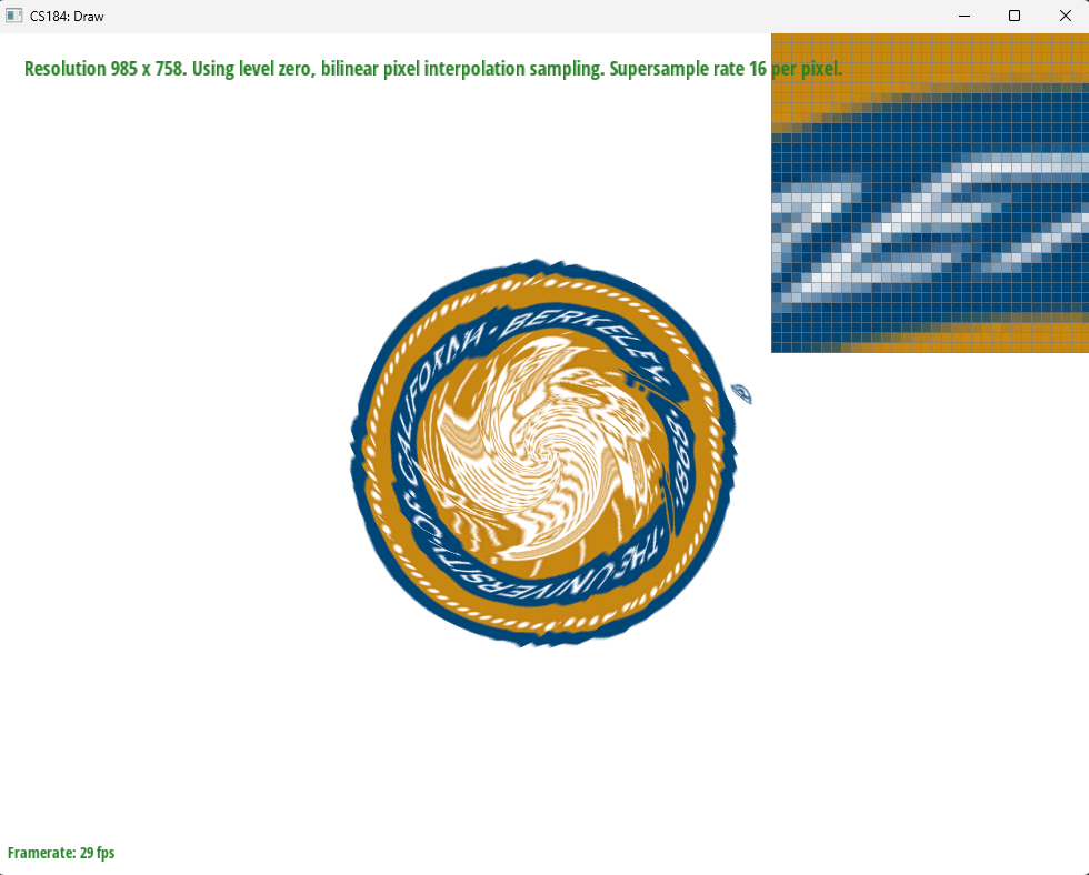
| 16x supersampling | 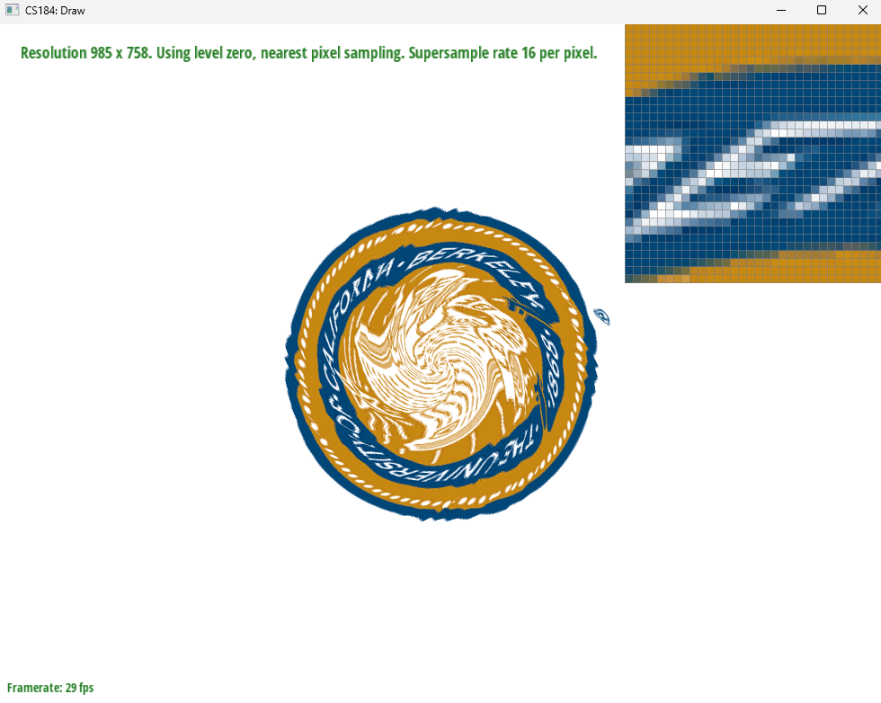
|
|
The bilinear pixel sampling images have smoother edges and fewer artifacts compared to the nearest sampling images with the same supersampling rate. The differences will be largest wehn the texture has a sharp cutoff between two colors. The example images given portray such a case since the white color of the “E” is different from the blue background of the seal. Nearest pixel sampling with no supersamplings struggles with the color transitions and so has some jaggies. Changing the bilinear sampling, and supersampling, help to antialias such that the bilinear pixel sampling with supersampling produces a far smoother image.
Task 6: Level Sampling
Sampling an image at the same resolution across the entire screen is not always effective: for instance, if an object is very far away, it will be sampled at a much lower frequency than a nearby object, which could create aliasing.
To solve this, we can use level sampling by precomputing mipmaps at various lower resolutions, and sampling textures from these mipmaps depending on how far apart two pixels are when converted to texture space.
For this project we implemented three types of level sampling:
L_ZEROonly samples from the original texture (Level 0) for the entire image. This is by far the simplest level technique, and requires the least computation and memory to determine the level that should be used at each position. However, the main drawback is potential aliasing as described above, since there is no additional support for antialiasing.L_NEARESTrounds the computed level to the nearest integer, and uses the mipmap corresponding to that level to sample the texture. This makes a balanced tradeoff between speed and antialiasing power, and uses more memory thanL_ZEROsince we now need to store mipmaps for multiple levels.L_LINEARtakes takes the two closest levels (using floor and ceiling), and uses bilinear interpolation to average out the color values retrieved from those two levels. This has the highest computation amount required, and results in the greatest amount of antialiasing.
To calculate the level, we use the following formula:
$$D = \log_2 ( \max ( \sqrt{(\frac{du}{dx})^2 + (\frac{dv}{dx})^2}, \sqrt{(\frac{du}{dy})^2 + (\frac{dv}{dy})^2}))$$
This formula uses the change in texture space from one pixel to the next to determine the level: if there is a greater change, a higher level is used (this represents a lower resolution mipmap used for far-away objects).
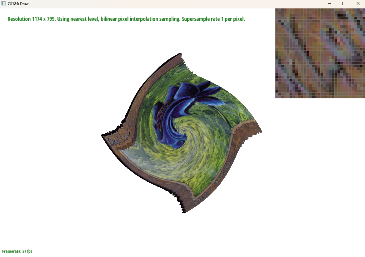
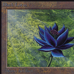
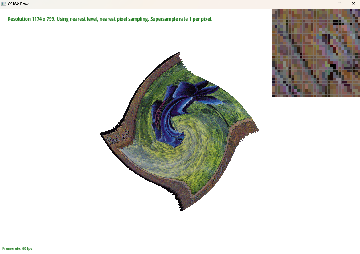
To illustrate the differences, we used the following reference image of an Alpha edition Black Lotus on the SVG transform originally used for the Berkeley seal:
L_ZERO and P_NEAREST

L_ZERO and P_LINEAR

L_NEAREST and P_NEAREST
L_NEAREST and P_LINEAR